INTERFACING PROCESSING WITH MY OUTPUT DEVICE BOARD
As mentioned previously in the output devices week that I will be using the light sensor circuit that I built and interface it with processing.
I have never used processing or any programing languages before that is why I decided to follow some online tutorial that help me get the project done.
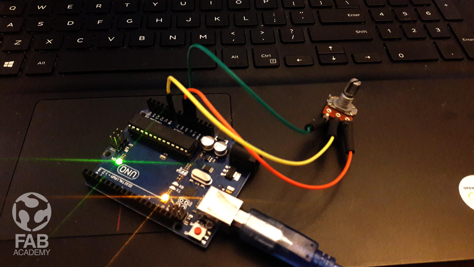
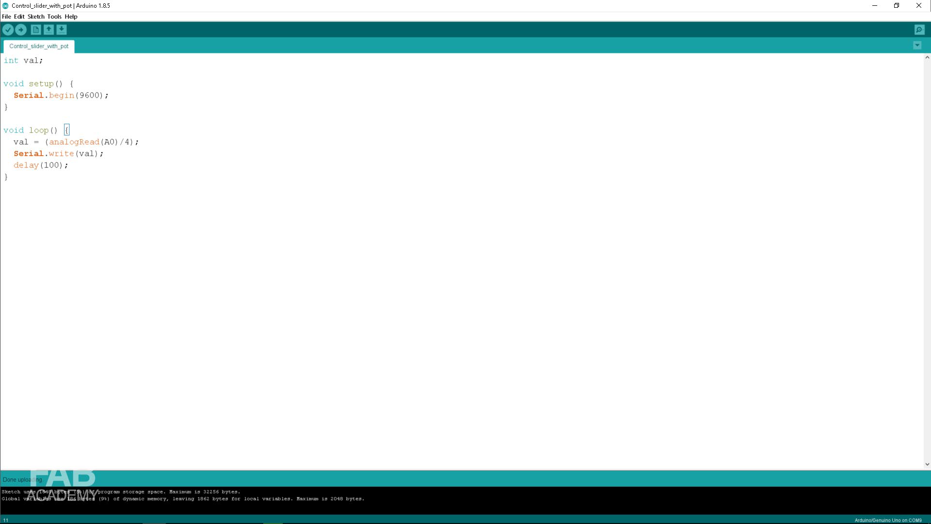
Initially my idea was to interface a potentiometer with processing so based on that I started prototyping my idea using Arduino UNO as shown in image # 01
But after that I changed my mind and decided to use my output devices board my goal of this project is to make a simple program using Processing that changes the color of a background based on the on board led light status so when the led light is off the background changes its color to dark gray and once it is on it changes its color to yellow
And since I had dedicated 2 pins on the Attiny44 for RX and TX I wanted to connect my laptop which will be running processing code wirelessly with my output devices
So to begin with I had to write two codes, one in Arduino programing environment for controlling the led light and second code using processing for controlling the background color .
Arduino code will be uploaded and stored on the Attiny44 microcontroller and as for processing code it will be running directly from my laptop.
To begin with, I started with writing the code that will be uploaded to the Attiny44 as mentioned before I used Ardunio IDE environment for writing the code. The idea of the code is to make the led light blink and send number 1 when the led is on and number 0 when the led is off.
However, after writing and uploading the code to my board I started seeing the led light blinking as shown in video # 09 and then after I was done with programming the board I started with writing processing code which will cause the background to change its color.
The idea of the code is to make it listen to the incoming data from my board so whenever the data is equal to 1 the background becomes yellow and this indicate that the led is on and when the incoming data equal to 0 the background turns its color to dark gray and that indicates the light is off.
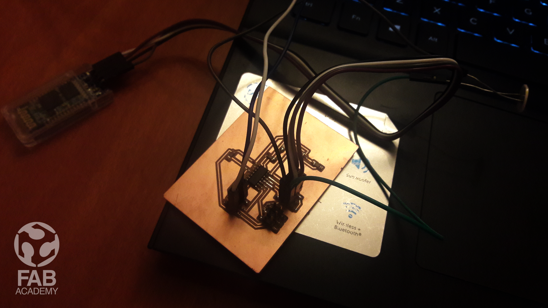
And once I was done with writing the code in processing I powered on the board using FTDI cable as shown in image #06 and I found that the led is blinking but the background in processing is not changing its color so to solve this problem I checked the schematic design again ( output devices week ) and read the data sheet. of the Bluetooth module and I found that I have to flip the RX and TX cable on my board in ordered to make it works.
And once I did that everything works fine as shown in video # 05 & video # 09
Below are the codes I used
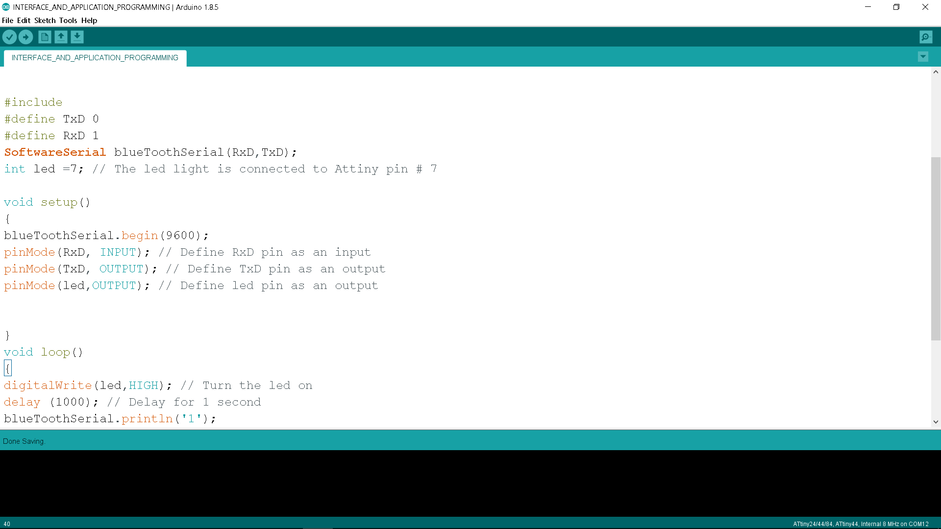
Below is Arduino code I used :
/* This code was modified by Georges Hanna Fab Academy 2018,INTERFACE AND APPLICATION PROGRAMING The code was modified Based on the below codes : https://forum.arduino.cc/index.php?topic=386417.0 https://create.arduino.cc/projecthub/mayooghgirish/arduino-bluetooth-basic-tutorial-d8b737 */ #include#define TxD 0 #define RxD 1 SoftwareSerial blueToothSerial(RxD,TxD); int led =7; // The led light is connected to Attiny pin # 7 void setup() { blueToothSerial.begin(9600); pinMode(RxD, INPUT); // Define RxD pin as an input pinMode(TxD, OUTPUT); // Define TxD pin as an output pinMode(led,OUTPUT); // Define led pin as an output } void loop() { digitalWrite(led,HIGH); // Turn the led on delay (1000); // Delay for 1 second blueToothSerial.println('1'); digitalWrite(led,LOW); // Turn the led off delay (1000); // Delay for 1 second blueToothSerial.println('0'); blueToothSerial.flush(); // Using flush to clear Bluetooth Buffer }
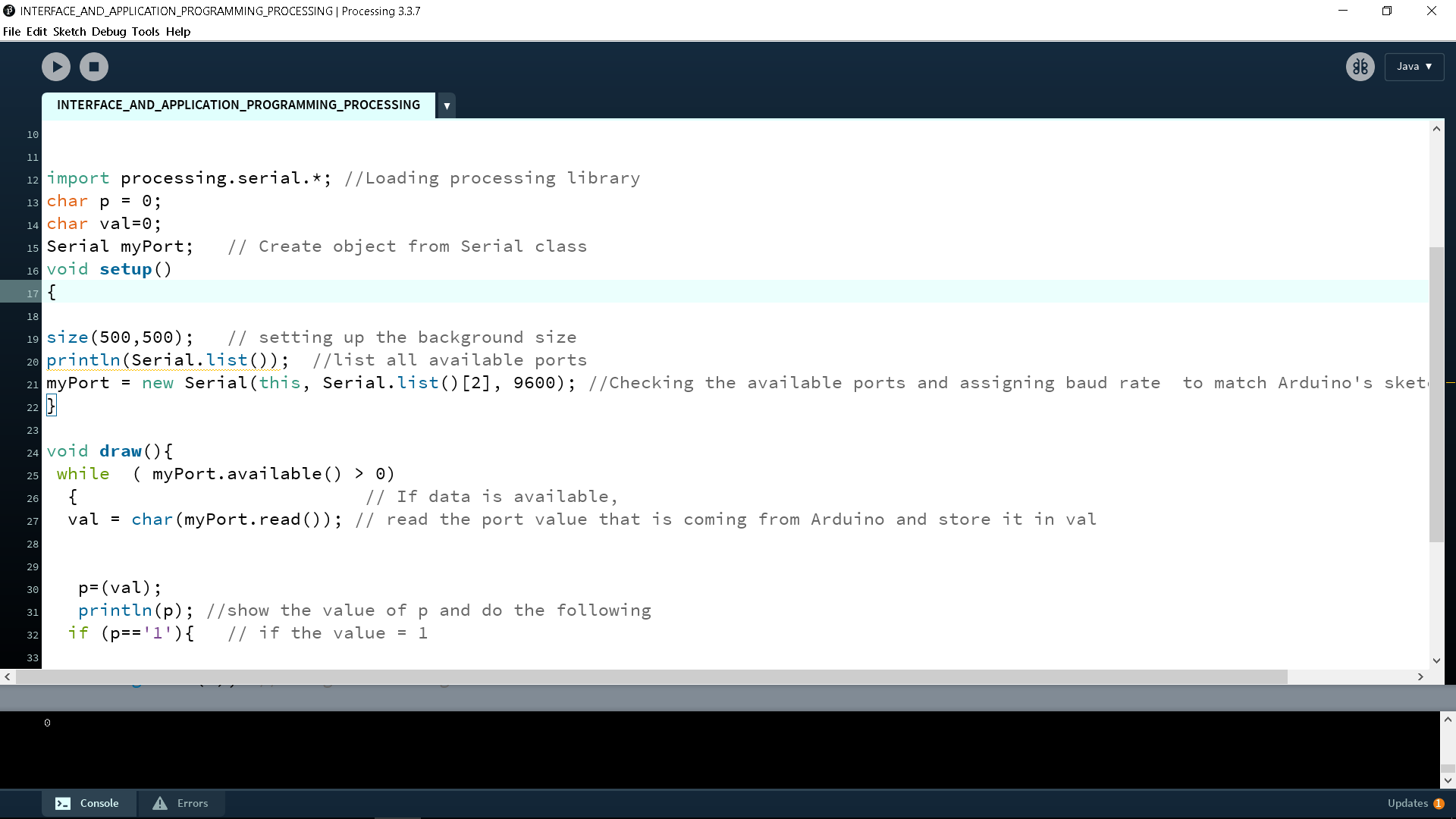
Below is Processing code I used :
    /*
  This code was modified by Georges Hanna Fab Academy 2018, INTERFACE AND APPLICATION PROGRAMMING.
  The code was modified Based on the below codes :
  https://abhikpal.github.io/blog/2013/10/05/getting-started-with-arduino-processing-serial-communication

  */


  import processing.serial.*; //Loading processing library
  char p = 0;
  char val=0;
  Serial myPort;   // Create object from Serial class
  void setup()
  {

  size(500,500);   // setting up the background size
  println(Serial.list());  //list all available ports
  myPort = new Serial(this, Serial.list()[2], 9600); //Checking the available ports and assigning baud rate  to match Arduino's sketch baud rate.
  }

  void draw(){
   while  ( myPort.available() > 0)
    {                           // If data is available,
    val = char(myPort.read()); // read the port value that is coming from Arduino and store it in val


     p=(val);
     println(p); //show the value of p and do the following
    if (p=='1'){   // if the value = 1

      background(255, 204, 0); //Change the background color to yellow
    }
    if (p=='0'){
      background(1);  //Change the background color

    }
      delay (1);
    }
    }
DOWNLOAD SECTION
+ INTERFACE_AND_APPLICATION_PROGRAMMING.ino DOWNLOAD .
+ INTERFACE_AND_APPLICATION_PROGRAMMING_PROCESSING.pde DOWNLOAD .